|
Switch to RUS |
|
|
|
О лаборатории |
|
Приборы |
|
Цейсс-600 |
|
Недавние результаты |
|
Публикации (последние 10 лет в ADS) |
|
В пресс-релизах САО |
|
ASPID |
Вернуться на страницу в САО  |
|
Last update: 22 Nov 2021 This page is designed by A.V. Moiseev moisav  sao.ru sao.ru
|
|
Лаборатория спектроскопии и фотометрии внегалактических объектов |
BTA primary focus adapter
Instrument status – general use
Responsible astronomer – Roman Uklein (ukleinsao.ru)
The BTA primary focus adapter (hereafter “Adapter”) is designed for off-axis guiding and telecentric illumination of the input of the installed equipment by various calibration light sources. In addition to the focal reducers SCORPIO and SCORPIO-2, it can also host other spectrographs with a weight up to 150kg and a working section no longer than 40 mm. Two main modules are available:
- GUIDING MODULE – correction of the position of the BTA telescope based on digital imaging, atmospheric transparency control, and control of the telescope focusing based on reference star photometry;
- CALIBRATION MODULE – telecentric illumination of the CCD-arrays of the mounted instruments with discrete and continuous spectrum sources.
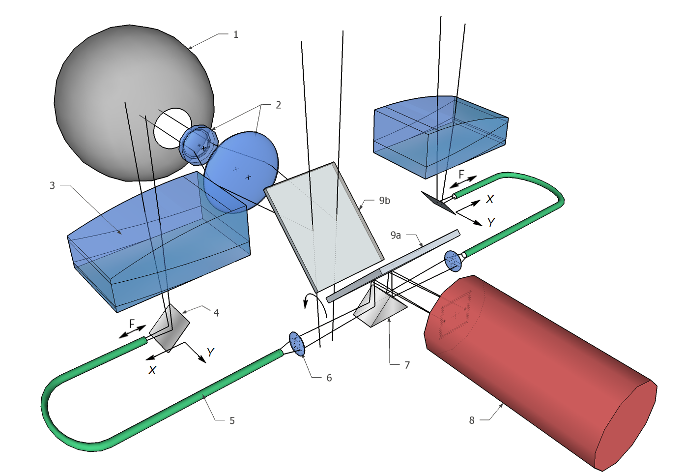 Optical scheme of the Adapter: 1 - integrating sphere, 2 - optics of the calibration illuminator, 3 - off-axis lens corrector, 4 - mirror, 5 - fiber bundle, 6 - optical fiber lens, 7 - reflective prism, 8 - guide camera, 9 - diagonal mirror (both positions shown): 9a - FIBERS, 9b - FIELD.
Parameters of the BTA primary focus adapter
1. GUIDING MODULE
An Atik Titan camera with a Sony ICX424 detector with a 7.4×7.4 micron element size and a 659×494 format is used as a guide. Depending on the position of the diagonal mirror of the Adapter, two main modes are available:- FIELD (direct field of view). The diagonal mirror in the FIELD position transmits the image of the main field of view to the guide, which makes it possible to identify the field, including positioning bright sources on the slit. The FIELD size in the guide is 3ʹ × 2ʹ.
- FIBERS (reference star images). In the FIBERS position, the light from the observed objects is received by the instruments mounted on the Adapter, and the guide receives the reference star images. The celestial sphere projected angular diameter of the fiber harness amounts to 54ʺ, and the field size for moving it is 10ʹ×4ʹ.5. Guidance field centers are located at a distance of 12ʹ from the centers of the fields of view of the system.
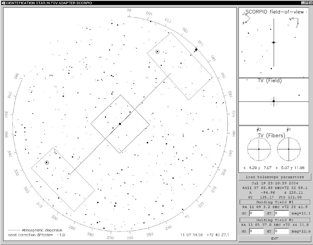 Guiding star search app interface
In addition to visualization of the image from the guide, the guidance software allows one to superimpose digital crosses and marks on the image. The captured image shows either the position of the slit in the FIELD with the observed source, or two crosses in the FIBERS guidance fields, with stars captured in their centers.
A magnitude range of 10m–15m is optimal for guiding. Guiding by stars fainter than 15m is possible only for good quality images and sufficient transparency. The limiting R band magnitude for a signal-to-noise ratio of S/N = 5 is approximately 17m. For guidance quality control, a plot can be viewed on the screen of the control computer showing the following parameters: the current extinction, reference star image size, and the azimuth and zenith correction values for the BTA telescope.
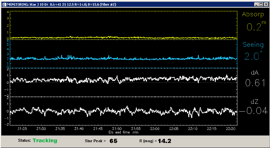 Guiding Star Monitoring
The input end of each of the guidance harnesses moves along the optical axis within 0-9.7 mm to focus the reference star, which allows one to correct the telescope focus during a long (more than one hour) series of spectral exposures if necessary. The presence of two calibration fields allows the focus control procedure to be performed on one of the stars while the other field is used to guide the telescope.
2. CALIBRATION MODULE
The calibration module consists of an integrating sphere (Ulbricht sphere), calibration illuminator optics and a control system integrated into the SCORPIO and SCORPIO-2 instrument control interfaces. The integrating sphere has two linear spectrum sources, a continuous spectrum source and 32 ports for installing LEDs as illuminators, which gives three calibration modes:- NEON: a lamp with He-Ne-Ar filling for calibrating the wavelength scale.
- QUARTZ: quartz halogen continuous spectrum lamp for creating a flat field.
- LEDS: A LED system that provides a continuous spectrum for a flat field with approximately uniform brightness over a wide range of wavelengths. This allows an equidistant illumination of the flat field in different spectral ranges and reduces parasitic scattered light in the blue region.
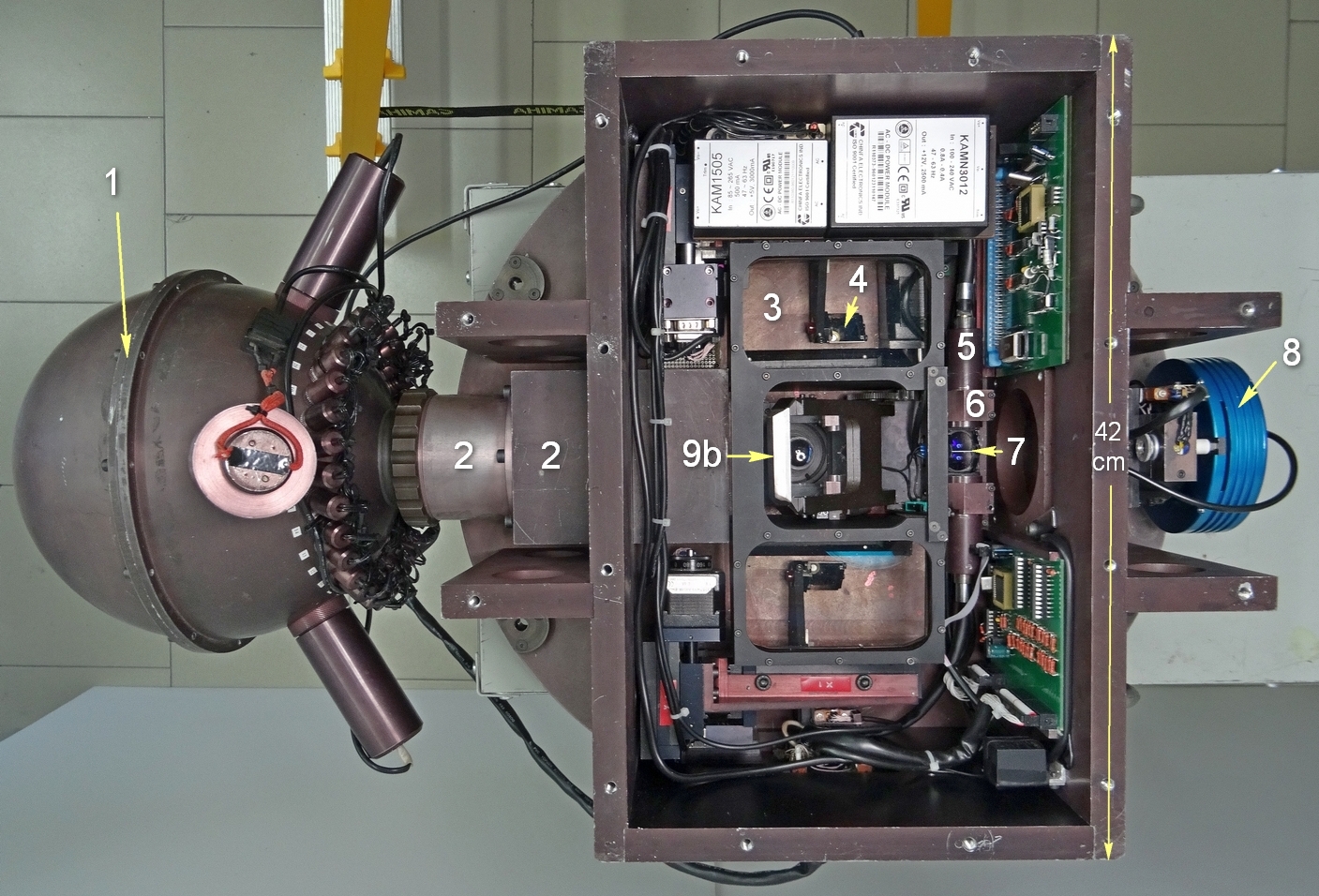 Photo of the Adapter with the cover removed: 1 - integrating sphere, 2 - optics of the calibration illuminator, 3 - off-axis lens corrector, 4 - mirror, 5 - fiber bundle, 6 - optical fiber lens, 7 - reflective prism, 8 - guide camera, 9 - diagonal mirror (both positions shown): 9a - FIBERS, 9b - FIELD.
Links:
- The Adapter is described in detail in the work of V.L.Afanasiev, V.R.Amirkhanyan, A.V.Moiseev, R.I.Uklein, A.E.Perepelitsin, the Astrophysical Bulletin, 2017, volume 72, No.4, pp.497–507 ( Russian PDF; arXiv:1711.03569 ).